
Of brakes and springs
5th September 2021
I can't resist quoting my favourite piece of A A Milne poetry, from Now we are six (apologies if I get it slightly wrong.)
Let it rain, who cares?
I've a train upstairs
With a brake which I make out of string
Sort of thing
Which works in jerks
Cos it stops in the spring
Which stops with the string
And the wheels all stick
So Quick
That it feels like a thing that you make with a brake
Not string.
So that's what I make when the day's all wet
It's a good sort of brake
But it hasn't worked yet.
And once again into a new month. Although the weather forecasters are promising us upper 20s temperatures this week, the nights are drawing slowly in.
I've had several days at the shed this week, partly because the repaint of Adams' big tractor, scheduled to occupy 2 weeks, has run into a third and his other rigs were busy. (Can't get the drivers y'know.) Andrew has largely been at work (he had Tuesday booked 'off' to take grandson back to his mother's and yet ended up taking chair at a Zoom meeting because another EMR colleague was unable to) leaving me to carry on with occasional help from outside.
Anyway, on the cement van, the end angle that Andrew elected to replace has been drilled, cut and later in the week primed and painted, allowing it to be refitted.
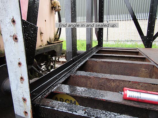
It's not quite as neat as the original (we don't have a countersunk bit correct for the M14 heads) but so far as the inside goes, that will disappear behind the interior lining of the end once the plywoods have been bolted in. Most of my time has been occupied with two loco jobs sat in the workshop, and since someone saw fit to assert on another forum that we don't do any 'real' railway engineering down here at Darley Dale I'll continue to give you more insights into the sort of railway engineering I have been doing for the last 43 years. As at Tuesday morning, though, I had a pallet in the back of the van waiting for DHL. It contained a composite brake block conversion kit - well to be exact 3 kits, one each for 3 locos, and some spare pieces. Their destination was overseas, and they had been ready since earlier last week but as the customer was arranging the transport, and I didn't know when they would collect, it was put in the van on the basis that wherever I was, so they would be. Thus at five to twelve I got a phone call from the driver to say he was outside the gates at Darley Dale. I at this point was trying to catch up on admin back at the Country Pile, and had just tucked in to a fresh bacon sandwich, but leapt into the van and dashed down. The DHL van was parked outside so I backed up behind it, he cleared some space and we hand-balled the pallet into the back, sorted the paperwork and off he went.
Back home for the rest of my lunch, then off to Sheffield, as the big order at the laser cutters was ready at last and I wanted to visit a seal specialist to sort out rings and such. I think I'll back-track a bit here. When I went back to being self-employed in 2009, I used this firm often: as it was only a mile from Briddon Towers (for new readers, that was our old semi in Sheffield). A counter sales person suggested I open an account and gave me an application form. One question asked how long I had been in business and I correctly answered it as only a couple of months. When I took it back, the sales person looked at this and said 'Oh we can't deal with you...' in a humiliating manner and with other customers in earshot.
They also sell tools, bearings, belts, pneumatic components, pulleys, chain and sprockets. Ever since that day every item I could buy from there, with the exception of o-rings and some cup seals I have made sure to buy somewhere else, and after this week, that might extend even to those. For having succesfully identified and produced the seals neccessary to refurbish the gearbox operating cylinder on Hudswell D1387, I asked for 3 different o-rings of about 6 inch diameter for the heat exchanger that urgently needs sorting. This was the result of detailed measurements that Andrew and I took - seperately - on Monday and then compared first thing Tuesday and since we couldn't quite decide which permutation would be optimal, opted for 3 choices for the 2 different locations. I was confident that these would probably have to be bespoke (especially as one is a rectangular section) but in past years this hasn't been a problem. This time it was the 'tut tut, they're very busy at the moment, it might take 4 or 5 days...' speech which didn't faze me. He wrote down my specs and said he'd ring with price and availability. Two days later he rang back, not to seek my authority to proceed but to ask whether I had really meant a 3/16 inch section ring 6mm in diameter. I tactfully pointed out that this was 6 inches, not 6mm (why would I mix metric and imperial in one line?) and he seemed relieved, but he still hasn't got back to me with any prices and delivery dates. I did deal with another supplier down south some years ago. I think it's time I enquired on them.
Amongst the pallet-full of profiles loaded at the laser cutters (thank heavens the export pallet had vacated) were the mount profiles for D1387's engine. The system for mounting engines is shamelessly based on Thomas Hill practice, which owes its origins to Rolls-Royce Sentinel, in that there is a front engine mounting using a pair of rubber 'sandwich' mounts set at an angle to the crankshaft centre-line and two rear mounts that secure to the flywheel housing. The front mounts are the same as Sentinel used and apart from cutting back to one safety link (there so that if a mount fails, the engine movement is limited) instead of two, the spirit of any TH or Sentinel engineer would recognise them. The rears however, are totally different. Sentinel adopted a unique Metalastik mount with which the engine is held in suspension. The resulting bracketry is complicated, and because it is in suspension, requires a bump stop so that if the mount sags or fails completely, the engine doesn't drop too far out of line. It may not be a serious problem with a propshaft with u/vs but remember on Sentinel chain drive locos the converter output goes straight into the gearbox
But this was 1950s practice. By the 1990s the collective wisdom is that you don't put the loads into suspension within the rubber, it's much better to be in compression. Consequently the unique Metalastik arrangement was not replicated by anyone else, and when Dunlop sold Metalastik it was one of those that soon disappeared. I had a stock that I used for spares orders but when in 1996 I was remanufacturing two locos for Sheerness, I took advice as to how better to do it. The result was a coned rear mount, (common to several different manufacturers) which the engine sits on, with an M16 bolt going through the centre, but on the underside a rebound washer is secured, spaced with washers to provide a 2-3mm gap under the mount. Thus if the engine starts bucking, the rebound washer limits its movement by compressing the underside of the mount the engine is secured to. In practice it seldom moves that much, but that's due to another part of the mounting system that I won't go into. Suffice it to say that 30 years after the Metalastik mount ceased manufacture (and there were two handed units, two sizes and several different grades of rubber to contend with, depending on engine weight) I know several preserved locos where the engines are sitting on the bump stops.
Back in the 90s, I had to get profiles made by flamecutting which was less accurate and required the brackets to be carefully set up, tacked, checked and finally fully welded before going out to machinists to be milled square and true and drilled to suit the cone mount centres. But laser cutting has changed all that. I send out a drawing of each part, complete with holes and incorporating tabs and slots wherever possible so that the mount can virtually hold itself together until Andrew tacks it up. I can even specify a hole correct for tapping to a thread form, rather than a simple clearance hole. So here's a few tasters and I'll let you see the installation as time goes on.
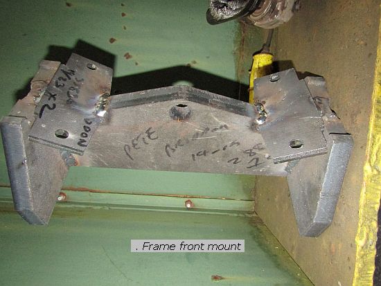
Here's the front mount, the part that ataches to the frame. It's actually sat on its end but I've turned the photo to its correct attitude. The sandwich mounts bolt to the two pads while the middle hole is for the safety link. The rear mounts attach to the frame are here...
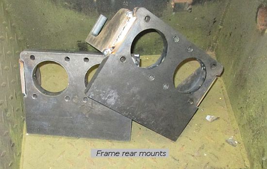
...and their counterpart that secures to the engine flywheel housing is this one.
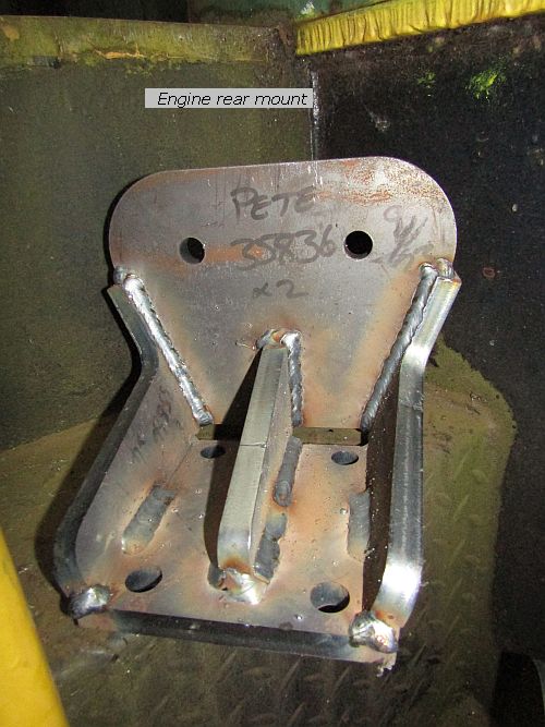
The two holes you see will be where the engine sits on the cone mount, located by the M16 bolt, while the 4 bolt holes in the plate on the bottom will secure the bracket to the flywheel housing. The ribs that secure the two together are tabbed through the two plates. Back to the front, and of these two, the upper/right one is the counterpart to the first photo - again the sandwich mounts bolt to the two plates while the back of the mount picks up on the timing case bolts as Cummins do. This bracket is virtually the same as those used on the Sheerness locos in 1996.
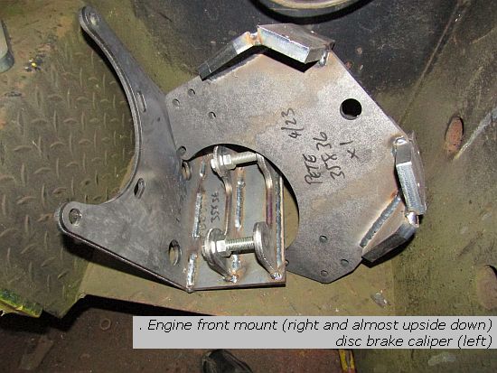
The bracket is is sat on however is something different. This loco is receiving a spring-apply/pressure-release parking brake, independent of the brake blocks. This too dates back to the Sheerness locos, when a good friend pointed out to me that un-manned radio controlled locos had no-one in the cab to apply the hand brake in the event of a problem, and a handbrake, since it too applies the brake rigging, can be compromised in the event of any form of mechanical failure in the rigging. So I duly embarked on fitting spring-apply/pressure release emergency/parking brakes (let's call them sa/pr before I wear my typing finger out) to a number of locos both radio and manual-only controlled. It was not without any incident. The disc was sized so that the force applied by the caliper, acting through the gearbox ratio, was sufficient to brake and hold a considerable tonnage on a gradient. But if that brake came on in an instant, it was sure to lock up the wheels and slide, so I had to arrange the pneumatics so that the caliper applied progressively. But then a loco working for Ford 'rolled away' on a slope when the driver applied the sa/pr brake and released the loco straight air. It didn't move far, rather his brake valve (which I had arranged as a pilot valve driving a relay valve for better response!) released the loco air quicker than my spring progressively took over. But unions will be unions and Ford spent a day or two adjusting the rate of application until everyone was content.
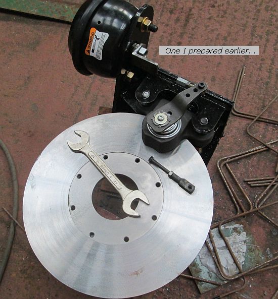
More recently I have fitted them primarily as parking brakes, either manually applied (as on 03 901) or as sa/pr, but with a smaller disc and quicker activation as they are not expected to be used to stop unbraked trains as well as themselves. And there, after all that history, is the mounting bracket for the one going on 1387 - the two bolts being to hold the two plates parallel during welding. Unfortunately the caliper and cylinder, though on order for several weeks, have not yet arrived, but in the meantime I can check that it picks up correctly on the holes around the gearbox input bearing and get it painted up ready. And here, for comparison 'is one I prepared earlier'...
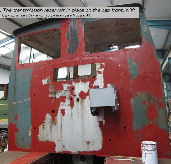
Back on the loco itself, with the cab front cleaned down and patch-primed, the transmission reservoir has been mounted. This is the tank that did so much commuting between the supplier and the Briddon Country Pile via the parcel company's depot in Stoke.
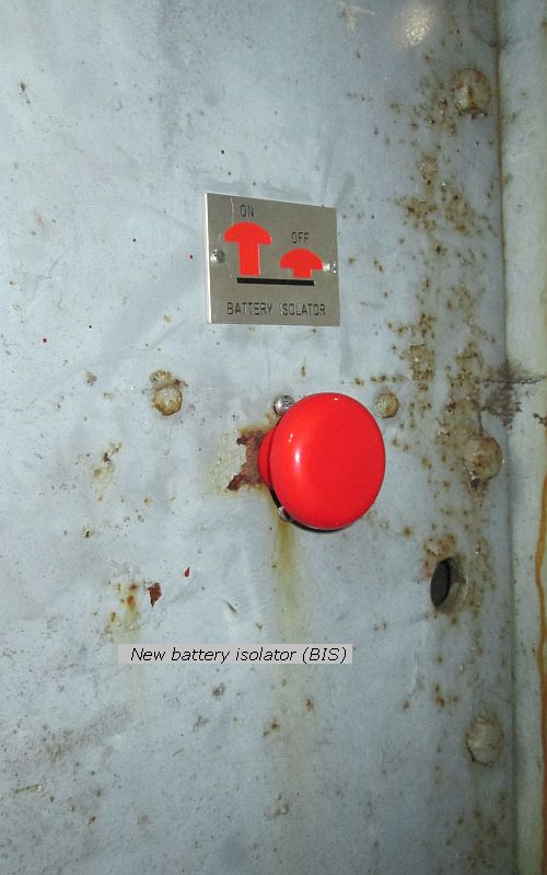
On the other side of the cab bulkhead is a manifold, which will operate the gearbox, clutch, horn and the sa/pr brake cylinder. The logic behind this will be in the electronics above, not inter-related valves and mechanisms. Nearby the battery master switch has been re-instated - I say that because I fitted the original in Blaenavon years ago but its replacement is two-pole and has adjacent a pictogram to remind how it is used.
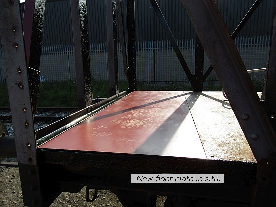
I can progress much of this work in advance of the engine going in, which brings us round to today's events. Although the engine ear-marked for 1387 has been in stock for a few weeks, it has two shortcomings, firstly it has an SAE2 flywheel and housing (the converter needs SAE1), and secondly a 'middle' drop sump (which wasn't even in my options book, so is a rare beast, perhaps) which fouls the chassis of 1387. Andrew and I have acquired in the past several 855s , one or more of which may get used to provide 'useful parts' for other engines, before getting rebuilt as core blocks. Today was a late start (as Andrew and Ben R had gone down to the Quorn swapmeet) and first task was to put the floor plate in to the cement van. Andrew had painted what would become the underside black last night (amazing how many flies managed to get stuck on it though) so as it was dry we slid in into place and hoped to weld it in later (though didn't get time).
Tom was fired up and shunted out one of the German flat wagons that has most of our stored engines on it, (in fact the other one was put over in to Road 1 in its stead) and in due course one spare 855 was lifted off the wagon on to the ground and we began to strip it.
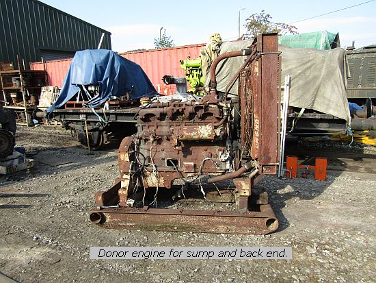
Andrew fears the crank on this may be a scrapper (the oil filler plate on the side is open to atmosphere and as the oil has been drained, there is nothing to stop the atmosphere causing rusting) but it has numerous parts worth what was paid for it and may yet be rebuilt in the future. For now we have removed the radiator, some bits of old bodywork and released most of the sump bolts, taken off the flywheel but ran out of time with the flywheel housing obstructing access to the remaining sump bolts. We'll come back to that.
And that brings us to a close of another week. Transport will re-appear in next week's blog, but beyond that anything might happen. Hopefully I'll be back next Sunday to tell you more. See ya then.