
Of a tale of two compressors.
21st June 2020
Hardly a mention of pandemic this week, and no prophecies iof doom for the heritage railway industry. A mix of recent work and anecdote.
The trouble with this week has been that most of has happened is not yet reportable. By which I mean that a lot of planning and negotiation has been going on behind the scenes which I hope will make for interesting reading - once everything has been settled. So I'll have to fall back on a few snippets and a bit of something I hadn't planned on.
Oh yes, I promised to report back on our attempt to use the plasma cutter to remove a broken tap. Answer: worked a treat. The plasma removed 85% of the tap, the remaining bits were easily knocked out, and the thread was barely touched, just needed another tap run through to clean it out.
On Wednesday we had some bad news filter through from our good neighbours by the shed. A contingent of 'travellers' had been evicted from council land at Bakewell and a number had taken up residence at a caravan site barely half a mile from the shed. I made some additional visits that evening just to check everything was undisturbed. News though was that the group had had an 'altercation' with the owners of the caravan site, a nearby pub (which had barely got itself sorted after the last round of floods to be kept closed by the pandemic - they must reckon things can't get any worse) which included a traveller's Range Rover being driven at pedestrians and just clipping one. As a result the police attended and remained on site after the travellers had reportedly threatened to get 20 more strong blokes to come and inflict GBH.
On Thursday the Peak Rail office forwarded an e-mail from a local councillor explaining what had occurred and saying that most of the travellers had set up on the DFS car park, which is right next to the top end of Darley Dale yard. Now, although I had walked round on Wednesday night I had not seen an encampment there, but it is a large car park. So shortly after, Steph and I went over to our friendly machinist to deliver a length of cold drawn seamless steel tube for use on a job, and returned via the shed. Those travellers at the caravan site were sill there, but so were the Police. At Darley the DFS car park contained nothing but a small number of customers' cars, staff vehicles and deivery lorries, so presumably the others had moved on. According to the email, the Police would be using S61 powers to escort the caravan site contingent out of the area. NIMBY, I know, but the last time I had contact with 'travelers' was in YEC days at Long Marston, and we lost several £000 worth of material overnight.
The concrete sleepers departed during the week. It's been too wet to tidy up outside and the crane has yet to be booked for a big move around though Andrew is developing a plan of where to put what. But I named this weeks edition about two compressors and I suppose I had better get on with it. Years ago I got an order from the MoD to prepare a scheme for installing additional compressors on the Ruston LSSH locos. Some of them had been through base overhaul at Hills and Baguleys and I think we did that then, but not all the fleet had been and with a view to upgrading them with train air, the MoD wanted a 'kit' design preparing that would take a compressor they had in stock. Having gone in with a finger-in-the-air price, I opted to pass the job to a little design consultancy which Cummins used and I had employed on some early YEC repower jobs.
Now maybe I should have been more specific in my requirements, but I work on the principle that if you're commissioning Michaelangelo, you don't tell him how to mix paints. They came back with a beautiful design: the compressor would sit on a cradle with a machined base, that would slide to and fro on another fabricated and machined support under the action of a specially machined screw thread and nut arangement. It was worthy of a lathe tool, one which you spun repeatedly as you turned something down to size, but a compressor, or alternator, or whatever else you have so-driven on the loco, is normally set up new, maybe checked after a few hours of running in case the belts stretch any, and thereafter are subject to an inspection from time to time and adjusted only if required. Besides, I had to supply the first-off kit and the machining cost alone would have exceeded my invoice value! I thanked them kindly, paid their bill and concluded that I should do it myself. Nowadays it is almost second-nature. With laser cut components you can cut slots so that the compressor can slide in line on the base, and I cut additional tabs and slots so that it all positions itself for welding. No two are ever quite the same though.
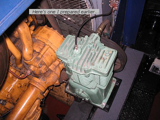
For example, here's one done for RMS to fit a 34ton Sentinel that had been repowered with a Cat engine. You can see that the holes are slotted almost to the end of the base and there are drive screws at the inside end that are used to push and hold the compressor to tension the belts.
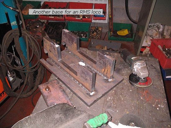
Here's another base, upside down, but again you can see the slots. Sometimes the compressor must stay still in order to stay within a casing line, and belt tension taken up with a second assembly. The compressor though must run with the correct rotation and maximum speed. (Aha, says somebody, but compressors run both ways, they're two stroke, not four. They compress either way, yes, but not all makes of compressor are designed to run in both directions, and their lubrication system may be uni-directional). So that usually means that one end or the other needs a new pulley with the right grooves and diameter. I once had the bright idea that all I needed to do was to weld 4 thick angles across the loco from one side to the other, spaced to form two grooves the spacings of the compressor base. The compressor was thus free to slide wherever neccessary, and clamp down with the aid of some thick washers. It didn't seem to work as I intended. The compressor kept vibrating loose. After several repeats I gave up and substituted a solid plate for the angles. This kept the compressor in one place all right: I got a call from site one morning that the compressor had disintegrated. Up until then, when the belt drive had stayed firm, the compressor performance had been amazing. Now I went over everything and discovered to my horror that somewhere along the way I had managed to overspeed the compressor by a factor of nearly two. No wonder it had pumped so furiously and at first worked itself loose!
Belts drive on their vee'd sides, not the bottoms: when we took over the class 14, someone had set up the alternator with an A grrove belt and pulley driven from a C groove pulley on the front of the engine. It probably worked with such low hp involved, but it was bad practice and way too slow to deliver much charge: I relocated it.
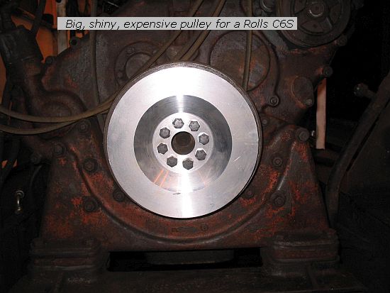
On this picture I had had a specially machined pulley made to fit the front of a Rolls-Royce C6S. It wasn't cheap, and now I would probably go for a stub shaft and commercial pulley as you'll see directly, but cost-wise there's not that much in it.
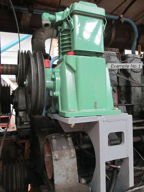
So, on loco number one, is a brand new compressor which had to be squeezed in to a restricted space over a dynamo (out the way while this photo was taken). It will take its drive by re-arranging an existing belt drive, but required a new pulley which was machined to fit.
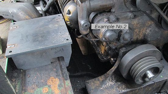
On loco number two I have not yet fitted the compressor, but it is a fully-overhauled BroomWade and will sit in one place so that it doesn't foul the casing doors. A seperate jockey pulley arrangement is in hand and to drive it I issued drawings for a stub shaft I had made before, without thinking to check the front flange on the crankshaft - after all, it's an N series Cummins, surely they're all the same? Well the stub shaft might fit a late 855, but the earlier 12 litre version was different. So an adaptor plate was lasered and the stub shaft fitted to that.

Now a taper-lock pulley is on as per the picture before, and I'm ready to line up the compressor belts and weld the base down.The big flywheely thing? That's what called a viscous damper. It's a sort of flywheel but the inside is well, viscous and moves about a bit, balancing things out.
So that's about it for this week. I'll be back next Sunday, all being well, and maybe something more constructive to say. Hope you're all keeping safe and well. See ya then.